
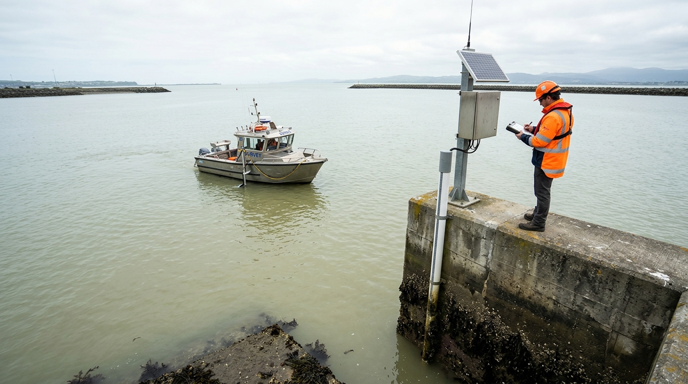
Bathymetric depth is not a measured quantity in the way that a distance or an angle is measured. It is a derived quantity, obtained by subtracting a water surface elevation from an acoustic range. The acoustic measurement may be precise to a few centimetres; the water surface elevation that converts it to a depth referenced to chart datum may carry uncertainty an order of magnitude larger. This asymmetry is the central technical problem in nearshore bathymetric survey, and it is resolved almost entirely through tide gauge strategy and vertical datum control.
Why the Water Surface Correction Dominates the Error Budget
A multibeam or single beam echo sounder measures the two-way travel time of an acoustic pulse and converts it to a slant range using a sound velocity profile. The result is a distance between the transducer and the seabed. To convert that distance into a depth below chart datum, the survey system must know the height of the water surface above chart datum at the precise time and location of each sounding, and the height of the transducer below that surface.
Vessel motion sensors and draft measurements handle the transducer offset with reasonable precision. The water surface term is where the error accumulates. Published uncertainty ranges for navigation project depth measurement make the hierarchy explicit: acoustic depth measurement uncertainty for depths under fifteen feet falls in the range of 0.05 to 0.1 feet, while tidal phase lag between a reference gauge and the work site can contribute uncertainties exceeding two feet in extreme cases. The tide correction, not the sonar, is the weak link.
Chart datum is a vertical reference surface so chosen that the tide seldom falls below it, conventionally the lowest astronomical tide. Every depth on a nautical chart or dredging survey is a height above that surface, which means the accuracy of the datum itself propagates directly into every reported depth.
Tide Gauge Placement: Covering the Survey Area Without Extrapolation
The International Hydrographic Organization's C-13 guidance establishes the governing principle for gauge placement: the survey area should be bracketed by tide stations so that extrapolation of water level reducers is minimized or eliminated. A gauge at one end of a survey corridor with open water beyond the other end forces the hydrographer to extrapolate a tidal signal into an area where the tide may have different phase and range. That extrapolation is an assumption, not a measurement.
Placement Relative to Hydrodynamic Controls
Gauges are positioned on either side of significant obstructions to tidal wave propagation, at intervals across shallow shelves, at estuarine constrictions, and at the boundaries between tidal and non-tidal regimes or between differing tidal types. In the Saudi Arabian context, the Arabian Gulf exhibits a mixed tidal regime with spatial variations in range and phase that are not uniform along the coast. A single gauge serving a long shoreline segment assumes a uniformity that the hydrodynamics may not support.
Redundancy and Overlap
IHO guidance calls for redundancy such that at least two gauges cover any portion of the survey area, providing both interpolation control and a fallback if one gauge fails. For supplemental stations intended to support datum determination rather than simply provide real-time water level, a minimum of thirty continuous days of data acquisition is specified, with data collection beginning at least four hours before survey operations and continuing at least four hours after they conclude.
Sensor Resolution and Calibration
Water level sensor resolution requirements scale with tidal range. For ranges up to five metres, the specified resolution is one millimetre or better; for ranges between five and ten metres, three millimetres; and above ten metres, five millimetres. Calibration must be traceable to a national or international standard, and the calibration should be checked after gauge recovery, not only before deployment.
Tidal Zoning: Interpolation as a Controlled Approximation
Zoning divides the survey area into regions within which a single water level correction, or an interpolated correction, is applied. It is a practical necessity because gauges cannot be deployed at every sounding location, but it is also a source of error that must be budgeted rather than ignored.
The IHO framework distinguishes between nearshore zoning, where gauges can bracket the area, and offshore zoning, where they cannot. In offshore zoning, time and range corrections to coastal gauge data must be estimated from co-tidal charts or ocean tide models. Nearshore, the zoning scheme should be based on observed water levels rather than assumed uniformity, with final zoning designed for maximum accuracy after the data are in hand.
The error introduced by zoning is directly related to the density of gauges and the spatial gradients in tidal phase and range. More gauges reduce zoning error but increase cost and logistical complexity. The hydrographer's task is to determine where the gradient is steep enough that additional gauges are justified by the error budget, and where a simpler scheme will not compromise the deliverable.
Datum Transformation: From Local Chart Datum to Ellipsoid
Traditional chart datum is defined by discrete reference points at shore-based tide gauges, typically the lowest astronomical tide observed at each station. This creates a datum surface that is discontinuous between stations and is not directly compatible with GNSS-derived ellipsoidal heights.
For RTK GNSS-based bathymetric survey, where the vessel's antenna height is known in the WGS84 ellipsoid and the water surface correction is applied through an ellipsoid-to-chart-datum separation model, the datum must exist as a continuous surface rather than a set of discrete station values. In Saudi Arabia, a continuous chart datum for the Arabian Gulf has been developed as a chart datum to WGS84 separation model, with separation values ranging from approximately −14.96 to −34.64 metres and uncertainties between 0.11 and 0.16 metres. This uncertainty range is significant relative to the IHO total vertical uncertainty allowance for special order surveys, which is approximately 0.25 metres at 95% confidence in shallow water.
IHO S-44 requires that the vertical datum used for tide prediction be related to the geodetic survey datum through prominent marks near the tide gauge, and that ellipsoidal heights of vertical reference marks be related to a geocentric reference system, preferably WGS84. Without this link, the chart datum is an isolated local surface with no traceable relationship to the positioning system used by the survey vessel.
Strategies That Optimize Datum Control
Effective Strategies
- Bracket the survey area with tide gauges on both sides of hydrodynamic controls, and operate at least two gauges covering every portion of the survey.
- Collect at least thirty continuous days of water level data at supplemental stations used for datum determination, with data spanning the full survey period plus four hours on each end.
- Verify sensor calibration after recovery as well as before deployment, and document the traceability chain to a national standard.
- Use a continuous chart datum separation model, where available, rather than interpolating between discrete station datums for RTK-based survey.
- Record tide stage and gauge reference for every survey line, enabling later diagnosis of whether a surface discrepancy originates from the seabed or from the water level correction.
- Cross-check RTK-derived water surface elevations against conventional gauge readings during operations, as a direct validation of the separation model in use.
Strategies That Degrade Results
- Extrapolating a single gauge's readings across a survey area with unmodeled phase lag. The resulting depth bias can exceed the sonar's own uncertainty by an order of magnitude.
- Using a chart datum defined only by shore-based reference points for RTK survey without a continuous separation model, introducing datum discontinuities into an otherwise continuous depth surface.
- Operating a gauge without leveling it to stable benchmarks, so that the datum itself moves between surveys.
- Accepting a gauge's published datum without verifying its epoch or adjustment history. Sea level rise between tidal epoch updates can introduce a constant bias into every reported depth.
- Deploying gauges only in accessible locations determined by logistics rather than by tidal hydrodynamics, producing a zoning scheme that does not reflect the actual water level field.
Technical Summary and Practical Implication
Nearshore bathymetric survey produces a depth surface that is only as defensible as its vertical datum. The acoustic measurement is rarely the limiting factor. Tide gauge placement determines whether the water surface correction is interpolated or extrapolated; zoning determines how that interpolation error is distributed across the survey; and datum transformation determines whether the resulting depths are referenced to a surface that is consistent, traceable, and compatible with GNSS positioning.
For dredging design, navigation channel clearance, and coastal engineering, the practical consequence is direct. A depth surface with an unquantified datum bias cannot support dredge payment measurement or clearance certification. Survey planning that treats tide gauge deployment and datum model selection as secondary to sonar specification inverts the actual error hierarchy. The defensible approach allocates effort to the water surface correction in proportion to its contribution to total uncertainty, which in most nearshore environments is the largest single term in the budget.